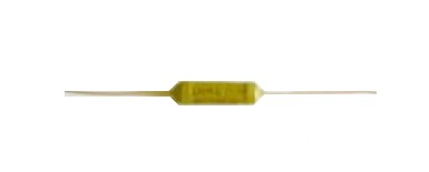
"SURE" BRAND WIRE WOUND RESISTOR - SSF
SILICON COATED FUSIBLE AXIAL LEAD TYPE
Introduction
'SURE' provides fusible resistor which fuse or blow if they are subjected to an abnormal spike of voltage / current. SSF Series is a low cost resistor fusible resistor which provides circuit protection for overload or component failure. The resistor will open quickly under continuous load and prevent circuit board from damage and hazards.
Features
• High Power to size ratio.
• High pulse load handling capabilities
• High temperature silicone coating with flame proof property.
• Non-inductive / Low inductive available on request
• Robust - Welded Construction
• Reliability against severity of environmental abuses.
• Instant Solder ability
• Resistant to Solvent
• Resistant to Alcohol
• ERTL type tested as per IS 8909
General Specifications
DESCRIPTION
SSF
01
SSF
02
SSF
2.5
SSF
04
SSF
06
SSF
09
SSF
12
SSF
15
SSF
20
Resistance (1) range , Series And tolerance (2) + 10 % + 5 %
E24 Series
0.01Ω - 0.05Ω
0.06Ω - 100kΩ
Rated dissipation at T amb = 70 0c
1 W
2 W
2.5 W
4 W
6 W
9 W
12 W
15 W
20 W
Temperature coefficient. (3)
R < 10Ω : 0 to +600ppm / 0c
R >10Ω - 80 to +140ppm / 0c
Operating temperature
- 400c to + 2000c
Basic specification
IEC60 115-1
Limiting voltage
√ (Pn x R)
Stability △ R/Rmax after:
Load
Climate tests
Resistance to soldering heat
Short time overload
+ 5.0% + 0.1 W + 1.0% + 0.05 W + 0.5% + 0.05 W + 2.0% + 0.1 W
(1) Special resistive values available on request
(2) Tolerances, 0.5, 1, 3 and 10% available on request
(3) Temperature coefficient, 30, 50 and 90ppm/0c, available on request
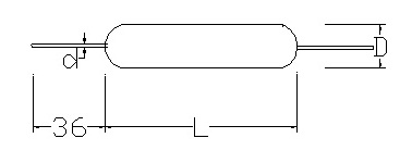
Mechanical Data
Table 1. Mechanical data
PRODUCT
L
D
d
SSF01
12.0 + 1.5
4.5 + 0.5
0.80 + 0.03
SSF02
14.0 + 1.5
5.5 + 0.5
0.80 + 0.03
SSF2.5
16.0 + 1.5
5.5 + 0.5
0.80 + 0.03
SSF04
18.0 + 1.5
6.5 + 0.5
0.80 + 0.03
SSF06
26.0 + 1.5
7.5 + 0.5
0.80 + 0.03
SSF09
34.0 + 1.5
8.5 + 0.5
0.80 + 0.03
SSF12
54.0 + 1.5
7.5 + 0.5
0.80 + 0.03
SSF15
54.0 + 1.5
8.5 + 0.5
0.80 + 0.03
SSF20
67.0 + 1.5
9.5 + 0.5
0.80 + 0.03
OPTIONS AVAILABLE
• Long lead (50 mm) on either side
• Extra Long Lead (65 mm) on either side.
• Thick lead (1.0 mm) on both sides.
Construction:
SSF: The resistor element is a resistive wire, which is wound, in a single layer, on a ceramic rod. Metal caps are pressed over the ends of the rod. The ends of the resistive wire and the leads are connected to the caps by welding. Tinned copper clad iron leads with poor heat conductivity are employed permitting the use of relatively short leads to obtain stable mounting without overheating. The resistor is coated with green silicon cement which is non-flammable, will not drip even at high overloads and is resistant to most commonly used cleaning solvents
Electrical Characteristics
DERATING: The power that the resistor can dissipate depends on the operating temperature.
Maximum dissipation (Pmax) in percentage of rated as a function of ambient temperature (Tamb)
Test and Requirements
Essentially all tests are carried out in accordance to the schedule of IEC publications 60115-1, category 40/200/56 (rated temperature range -40 to +2000c; damp heat, long term, 56 days and along the lines of IEC publications 60068-2); "Recommended basic climatic and mechanical robustness testing procedure for electronic components" and under standard atmosphere conditions according to IEC 60068-1 subclause 5.3, unless otherwise specified.
Table 8. Test and requirements
TEST
PROCEDURE
REQUIREMENTS
Temperature coefficient
Between - 400c and + 2000c:
R < 10Ω
R >10 Ω
0 to 600 ppm/0c
- 80 to +140 ppm /0c
Rated Load
Rated wattage for 30 minutes
+ (1% + 0.05W)
Short time overload
2.5 times the rated wattage for 5 sec
△/Rmax + 2% +0.1
Insulation Resistance
500 V DC
31000MW
Robustness of
terminations:
Tensile all samples
Bending half number of
samples
Torsion other half
number of samples
Load 10 N; 10 s
Load 5 N; 4 x 900c
2 x 1800c in opposite
directions
No visual damage
△ R/Rmax + 0.5% +0.05
Solderability
(after ageing)
16 h at 1550c; leads immersed in flux 600, leads immersed 2 mm for 2 + 0.5 s in a solder bath at 235 + 50c
Good tinning;
( > 95% covered)
No Visible Damage
Resistance to
soldering heat
Thermal shock: 3 s;
100c; 2.5 mm from body
△R/Rmax + 0.5% + 0.05
Rapid change of
temperature
30 minutes at - 400c and 30 minutes at + 2000c; 5 cycle
No visible damage
△ R/Rmax + 1% + 0.05
Vibration
Frequency 10 to 500 Hz
(1 to 7W) and 10 to 55 Hz
(10 to 20W),displacement
0.75 mm or acceleration 10 g, three directions;
total 6 h (3x2 h)
No visible damage
△ R/Rmax + 0.5% + 0.05
Incombustibility
6 times the Rated wattage for 5 minutes
Not flammable
NOTE : Fusible resistors are not standard resistor types and each type of fusible resistor must be designed to suit a particular application.
Data required to design a fusible resistor are:
1. The type you require -
Ceramic Encased or Axial Lead Type
2. Resistance in ohms.
3. Power rating in terms of watts.
4. Tolerance.
5. Fusing current - The current at which the resistor must fuse or blow.
6. Fusing time - The duration within which the resistor must fuse or blow, on being subjected to the fusing current.
At SURE if no special data is provided, a fusible resistor can be made as per the following chart :
FUSING CHARACTERISTICS :
POWER
FUSING TIME
MAX
16 X Wattage
1 min
20 X Wattage
40 sec
24 X Wattage
30 sec
28 X Wattage
20 sec
32 X Wattage
15 sec
TYPICAL APPLICATIONS :
As mentioned previously a fusible resistor is a dual purpose component -
(a) In normal conditions it functions as a resistor.
(b) In high overload conditions it acts as a fuse/safety device.
In some countries all types of ceramic encased type resistors are wrongly called as fusible resistors. It must be clearly understood that fusible resistors are special purpose, specially designed resistors and are produced mainly in two configurations -
(a) Ceramic encased type (SCF) and
(b) Flame retardant silicone coated axial lead type.