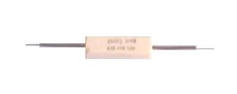
"SURE" BRAND WIRE WOUND RESISTOR - SCA SERIES
CERAMIC ENCASED AXIAL LEAD TYPE - Professional Grade
Features:
· High Power dissipation in small volume
· High surface insulation property
· Completely fire proof and welded construction
· Available in PCB type and capacitor type terminals
· Formed leads available on request
· Low inductance type available on request
· Long leads also available
General Specifications:
|
DESCRIPTION |
SCA03 |
SCA04 |
SCA06 |
SCA09 |
SCA12 |
SCA20 |
|
Resistance range, Series And tolerance (1) ± 10 % ± 5 % |
E24 Series |
|||||
|
0.01 W - 0.05 W |
||||||
|
0.06 W - 100 KW |
||||||
|
Maximum dissipation at Tamb = 40 °C |
03 W |
04W |
06 W |
09 W |
12 W |
20 W |
|
Maximum permissible voltage (volts DC or RMS) |
V =√ (Pn × R) |
|||||
|
Insulation voltage |
> 2000 V |
|||||
|
Temperature coefficient. (2) |
R < 10 W: 0 to +600ppm/°C |
|||||
|
Operating temperature |
R ≥ 10 W: -100 to +150ppm/°C - 55 °C to + 275 °C |
|||||
|
Stability DR/Rmax after: Lead, 1000 hours Climate tests Short time overload |
± 5.0% + 0.1 W ± 3.0% + 0.05 W ± 4.0% + 0.05 W |
|||||
(1) Tolerances, 1% and 3% available on request
(2) Temperature coefficient, 30, 50 and 90ppm/°C, available on request
Mechanical Data:
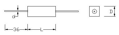
Table 1
|
TYPE |
L |
D |
d |
|
SCA03 |
15 ± 1.5 |
7.5 ± 0.8 |
0.81 ± 0.03 |
|
SCA04 |
25 ± 1.5 |
7.5 ± 0.8 |
0.81 ± 0.03 |
|
SCA06 |
25 ± 1.5 |
9.5 ± 0.8 |
0.81 ± 0.03 |
|
SCA09 |
38 ± 1.5 |
9.5 ± 0.8 |
0.81 ± 0.03 |
|
SCA12 |
38 ± 1.5 |
11.0 ± 0.8 |
0.81 ± 0.03 |
|
SCA20 |
50 ± 1.5 |
11.0 ± 0.8 |
0.81 ± 0.03 |
Dimensions in mm
Construction
SCA: The resistor element is a resistive wire, which is wound, on ceramic rod. Tinned copper leads are connected to the caps by welding. The resistor body is housed in a rectangular ceramic case with a special inorganic potting which is non-flammable, will not melt even at high overloads and is resistant to most commonly used cleaning solvents and moisture.
Electrical Characteristics
DERATING
The power that the resistor can dissipate depends on the operating temperature; see below
Fig - Maximum dissipation (Pmax) in percentage of rated power as a function of the ambient temperature (Tamb)
Applications:
The SCA Series is recommended for the use where occasional overload is upto 125% for long time [upto 2 Hrs.] are probable. This Series is also preferred for aesthetic value. The fusible resistors (SCF) are also available in this series.
Test and Requirements
Essentially all tests and requirements present in table below follow the schedule of IEC standard publication 60115-1, 60115-4 and 60068.
|
TEST |
PROCEDURE |
REQUIREMENTS |
|
Insulation resistance |
500 V (DC); during 1 minute V-block method |
Rins min 100 MW |
|
Voltage proof on insulation
|
1000 V (RMS); during 1 minute V-block method. |
No breakdown or flashover |
|
Temperature Coefficient |
Between -55 °C at +275 °C: R < 10 W R ≥10W |
0 to +600ppm/°C + 150 to - 100ppm/°C |
|
Short time overload |
5 times the rated wattage for 5 sec |
DR/Rmax: ±2% +0.05W |
|
Robustness of terminations:
Tensile all samples
Bending half number of samples
Torsion other half Number of samples |
Load 10N; 10 s
Load 5N; 4× 90°
3×360° in opposite Directions |
No visible damage DR/Rmax; ±2% + 0.05W |
|
Solderability (after ageing) |
16h at 155 °C, leads Immersed in flux 600, leads immersed 2 mm for 2 ± 0.5 s in a solder bath a 235 ± 5 °C |
Good tinning; No damage DR/Rmax; ±0.5% ±0.05W |
|
Resistance to Soldering heat |
Thermal shock; 3s, 350 °C; 6mm from body |
DR/Rmax; ±4% + 0.05W |
|
Rapid change of temperature |
30 minutes at 55 °C and 30 minutes at + 275 °C; 5 cycles |
No visual damage DR/Rmax; ± 5% +0.05W |
|
Climate sequence:
Dry heat
Damp heat (accelerated) 1st cycle
Cold
Damp heat (accel) remaining cycles |
16h, 275 °C
24h; 25 °C to 55 °C; 90% to 98% R.H.
2h; - 65 °C
6 days; 55 °C; 90% to 98% R.H; |
DR/Rmax; ±3%+ 0.05W |
|
Damp heat (steady state) |
56 days; 40 °C; 90 to 95% RH Loaded with 0.01 Pn |
DR/Rmax; ±5% +0.05 |
|
Endurance 40 °C |
1000 hours load with Pn or Vmax 1.5h ON 0.5h OFF |
No damage DR/Rmax ±5% +0.1W |
| HOME | | PRODUCT RANGE | | PRODUCT PHOTOS | | CONTACT US |
| QUOTATION FORM | | CUSTOMER PROFILE | | COMPANY PROFILE |